What you can make
Each of these was made in Benchsmith on a phone: pick the bar, then add the operations in the order you'd machine them. You get the 3D part, a dimensioned drawing and the process sheet, ready for the shop floor. Tap Open a copy to change one into your own part.
Reference and design aid. Check every size before you cut metal.
Round bar: everyday parts
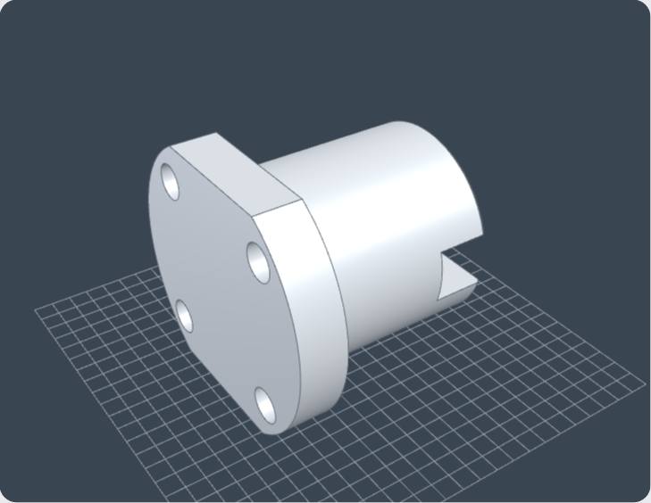
Drive dog
Flange with two flats, four bolt holes through it, a slot across the end.
Process sheet: Ø70 × 60 round bar, 6 ops
- Op 10 Turn Turn Ø50 × 48 long from the right end.
- Op 20 Mill Mill two flats 5 deep (60 across flats), 0 to 12 from the left end, at 0°.
- Op 30 Drill Drill 4 × Ø9 × 12 deep, flat bottom, on PCD 56, start 45°. Left end, centre X0 Y0 (holes A–D)
- Op 40 Mill Mill a slot 14 wide, 14 deep. Right end, X-32 Y0 to X32 Y0.
- Op 50 Drill Drill Ø5 × 8 deep, flat bottom. Right end, X0 Y0 (hole E)
- Op 60 Turn Chamfer the right end 1 × 45°.
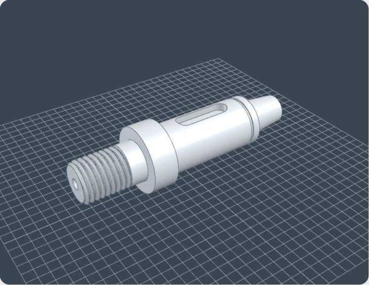
Keyed motor shaft
Threaded end, a collar, an h6 bearing seat with a keyway and a circlip groove, a tapered end, centre hole.
Process sheet: Ø35 × 112 round bar, 9 ops
- Op 10 Turn Turn Ø32 full length.
- Op 20 Turn Turn Ø20 × 30 long from the left end.
- Op 30 Turn Turn Ø25 h6 (+0.000 / −0.013) × 70 long, starting 42 from the left end.
- Op 40 Turn Taper from Ø14 at the right end to Ø18, 20 long (half angle 5.71°).
- Op 50 Turn Cut thread M20×2.5-6g, 22 long from the left end of the Ø20 run.
- Op 60 Turn Groove for a DIN 471 circlip (shaft Ø25): Ø23.9 × 1.3 wide, starting 87 from the left end.
- Op 70 Mill Mill a keyway 8 wide × 4 deep, 28 long (DIN 6885 A for Ø25: key 8 × 7), 52 to 80 from the left end, at 0°.
- Op 80 Turn Chamfer the left end 1.5 × 45°.
- Op 90 Turn Centre drill the left end A2.5/5.3 DIN 332 (for Ø20).
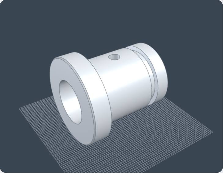
Flanged bush
A k6 press fit under a flange, bored through, an oil hole into the bore, an O-ring groove.
Process sheet: Ø45 × 43 round bar, 7 ops
- Op 10 Turn Turn Ø40 full length.
- Op 20 Turn Turn Ø30 k6 (+0.015 / +0.002) × 35 long from the right end.
- Op 30 Turn Bore Ø20 thru from the left end.
- Op 40 Drill Drill Ø5 × 5 deep from the top, flat bottom. Side, 23 from the left end, at 0° (hole B).
- Op 50 Turn O-ring groove for a 2.62 section (static): 2.1 deep × 3.65 wide, starting 33 from the left end.
- Op 60 Turn Chamfer the left end 0.5 × 45°.
- Op 70 Turn Chamfer the right end 0.5 × 45°.
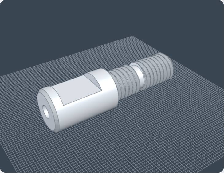
Threaded pin with flats
Head with a tapped hole, two spanner flats, an M12 thread with an undercut behind it.
Process sheet: Ø20 × 55 round bar, 8 ops
- Op 10 Turn Turn Ø16 full length.
- Op 20 Turn Turn Ø12 × 30 long from the right end.
- Op 30 Turn Undercut Ø9.8 × 2.5 wide, starting 37 from the left end.
- Op 40 Turn Cut thread M12×1.75-6g, 30 long from the right end of the Ø12 run.
- Op 50 Mill Mill two flats 3 deep (10 across flats), 4 to 19 from the left end, at 0°.
- Op 60 Drill Drill Ø5 × 12 deep, 118° point, tap M6×1. Left end, X0 Y0 (hole A)
- Op 70 Turn Chamfer the left end 1 × 45°.
- Op 80 Turn Chamfer the right end 1 × 45°.
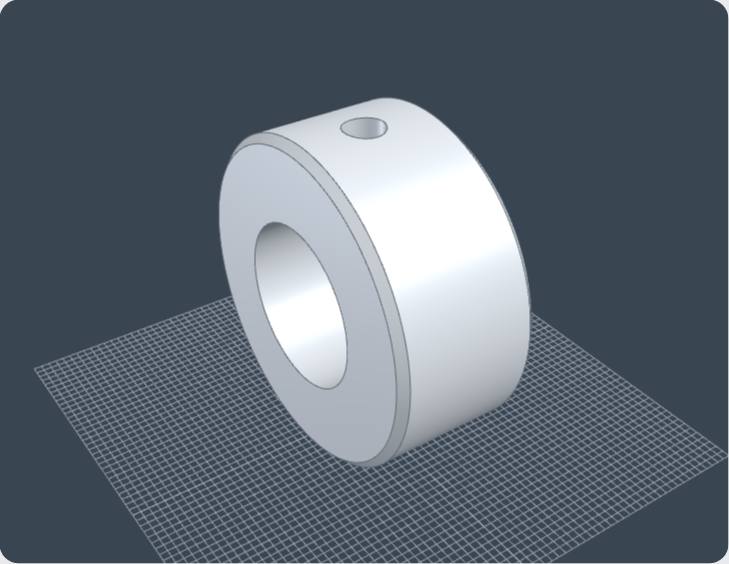
Shaft collar
Bored to slide on a Ø20 shaft, a tapped grub-screw hole into the bore.
Process sheet: Ø42 × 18 round bar, 5 ops
- Op 10 Turn Turn Ø40 full length.
- Op 20 Turn Bore Ø20 thru from the left end.
- Op 30 Drill Drill Ø5 × 10 deep from the top, flat bottom, tap M6×1. Side, 9 from the left end, at 0° (hole B).
- Op 40 Turn Chamfer the left end 1 × 45°.
- Op 50 Turn Chamfer the right end 1 × 45°.
Round bar: complex parts
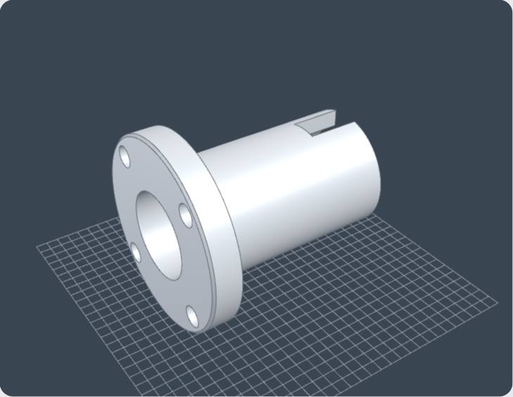
Flanged sleeve
Bored right through, a bolt flange, a notch through the wall at the far end.
Process sheet: Ø80 × 90 round bar, 5 ops
- Op 10 Turn Turn Ø50 × 78 long from the right end.
- Op 20 Turn Bore Ø36 thru from the left end.
- Op 30 Drill Drill 4 × Ø9 × 12 deep, flat bottom, on PCD 66, start 45°. Left end, centre X0 Y0 (holes B–E)
- Op 40 Mill Mill a slot 12 wide, 22 deep. Right end, X0 Y8 to X0 Y34.
- Op 50 Turn Chamfer the left end 1 × 45°.
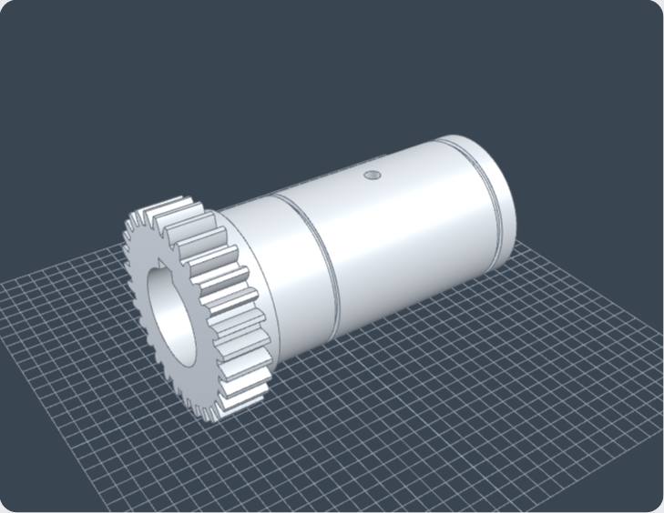
Gear shaft
30-tooth gear on the end, a groove and a DIN 471 circlip groove, bored through with a keyway in the bore, an M6 set-screw hole into the bore.
Process sheet: Ø66 × 110 round bar, 9 ops
- Op 10 Turn Turn Ø64 × 14 long from the left end.
- Op 20 Turn Turn Ø52 × 96 long from the right end.
- Op 30 Turn Turn Ø48 × 90 long from the right end.
- Op 40 Turn Bore Ø30 thru from the right end.
- Op 50 Turn Undercut Ø45 × 1.5 wide, starting 40 from the left end.
- Op 60 Turn Groove for a DIN 471 circlip (shaft Ø48): Ø45.5 × 1.85 wide, starting 102 from the left end.
- Op 70 Gear Cut 30 teeth, module 2, 20° pressure angle, 14 wide, 0 to 14 from the left end (tip Ø64, pitch Ø60, root Ø55). Dividing head (40:1): 1 1/3 turns per tooth. Involute cutter: check the cutter chart.
- Op 80 Drill Drill Ø5 × 9 deep from the top, flat bottom, tap M6×1. Side, 70 from the left end, at 0° (hole B).
- Op 90 Mill Cut a keyway 8 wide in the left end bore (Ø30), 3.3 deep from the bore wall (33.3 over the bore and keyway), the whole bore, at 0° (DIN 6885 A for Ø30: key 8 × 7): slot or broach.
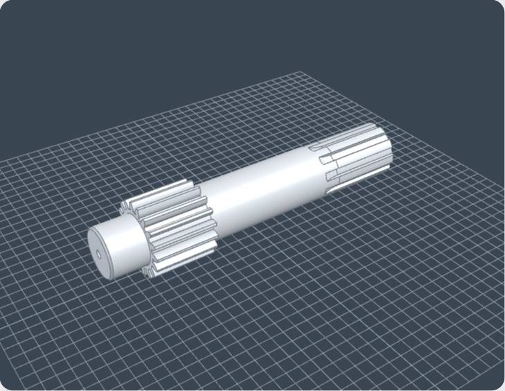
Splined pinion shaft
18-tooth pinion, 10 straight splines on the end running out on a Ø63 cutter, centre holes both ends.
Process sheet: Ø62 × 260 round bar, 9 ops
- Op 10 Turn Turn Ø60 × 260 long from the left end.
- Op 20 Turn Turn Ø40 × 30 long from the left end.
- Op 30 Turn Turn Ø45 × 180 long from the right end.
- Op 40 Turn Chamfer the left end 1.5 × 45°.
- Op 50 Turn Chamfer the right end 1.5 × 45°.
- Op 60 Gear Cut 18 teeth, module 3, 20° pressure angle, 50 wide, 30 to 80 from the left end (tip Ø60, pitch Ø54, root Ø46.5). Dividing head (40:1): 2 2/9 turns per tooth. Involute cutter: check the cutter chart.
- Op 70 Mill Mill 10 splines 7 wide, Ø45 outside, Ø39 root, 200 to 260 from the left end, Ø63 cutter (runs out over 14.04). Dividing head (40:1): 4 turns per spline (36° apart).
- Op 80 Turn Centre drill the left end A3.15/6.7 DIN 332 (for Ø40).
- Op 90 Turn Centre drill the right end A3.15/6.7 DIN 332 (for Ø45).
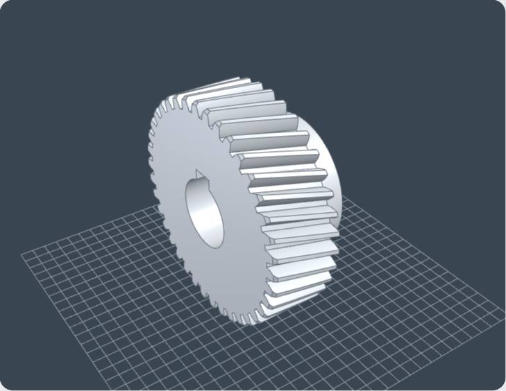
Helical gear
38 helical teeth, 15° right hand, normal module 2, on a hub, bored with a keyway in the bore.
Process sheet: Ø86 × 40 round bar, 6 ops
- Op 10 Turn Turn Ø82.68 full length.
- Op 20 Turn Turn Ø50 × 15 long from the right end.
- Op 30 Turn Bore Ø25 thru from the left end.
- Op 40 Gear Cut 38 helical teeth, normal module 2, helix 15° right hand, 20° pressure angle (normal), 25 wide, 0 to 25 from the left end (pitch Ø78.68, tip Ø82.68, root Ø73.68, transverse module 2.071). Lead 922.5: gear the table to it (change gears not worked out here). Dividing head (40:1): 1 1/19 turns per tooth. Involute cutter for 42.2 teeth (z ÷ cos³β): check the cutter chart.
- Op 50 Mill Cut a keyway 8 wide in the left end bore (Ø25), 3.3 deep from the bore wall (28.3 over the bore and keyway), the whole bore, at 0° (DIN 6885 A for Ø25: key 8 × 7): slot or broach.
- Op 60 Turn Chamfer the left end 1 × 45°.
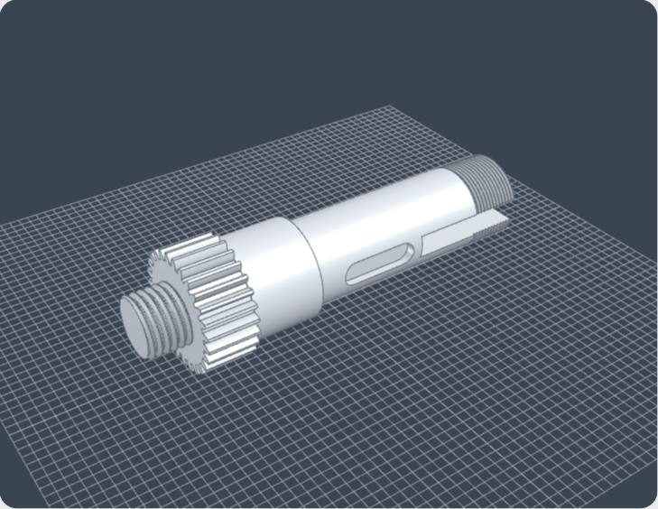
Forked spindle
Threads both ends, a 27-tooth gear, a fork slot across the threaded end and a DIN 6885 keyway.
Process sheet: Ø60 × 200 round bar, 9 ops
- Op 10 Turn Turn Ø58 × 200 long from the left end.
- Op 20 Turn Turn Ø30 × 20 long from the left end.
- Op 30 Turn Turn Ø50 × 35 long, starting 45 from the left end.
- Op 40 Turn Turn Ø42 × 120 long from the right end.
- Op 50 Turn Cut thread M30×3.5-6g, 20 long from the left end of the Ø30 run.
- Op 60 Turn Cut thread M42×2-6g, 25 long from the right end of the Ø42 run.
- Op 70 Gear Cut 27 teeth, module 2, 20° pressure angle, 25 wide, 20 to 45 from the left end (tip Ø58, pitch Ø54, root Ø49). Dividing head (40:1): 1 13/27 turns per tooth. Involute cutter: check the cutter chart.
- Op 80 Mill Mill a slot 12 wide, 60 deep. Right end, X-30 Y0 to X30 Y0.
- Op 90 Mill Mill a keyway 12 wide × 5 deep, 40 long (DIN 6885 A for Ø42: key 12 × 8), 95 to 135 from the left end, at 90°.
Square / flat bar: everyday parts
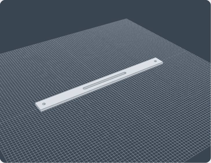
Slotted flat bar
Two bolt holes 550 apart and an adjusting slot between them.
Process sheet: 600 × 50 × 10 block, 3 ops
- Op 10 Drill Drill Ø11 thru. Top face, X25 Y25 (hole A)
- Op 20 Drill Drill Ø11 thru. Top face, X575 Y25 (hole B)
- Op 30 Mill Mill a slot 12 wide, thru. Top face, X200 Y25 to X400 Y25.
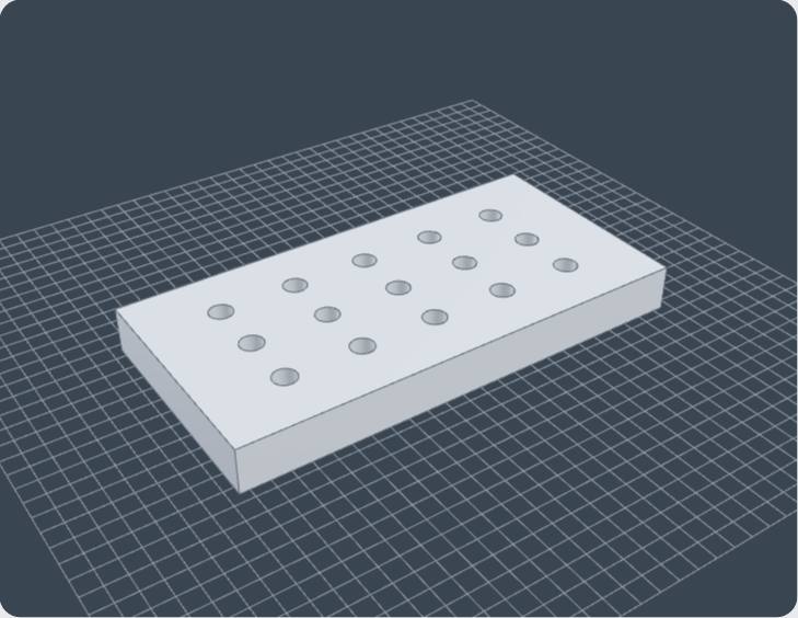
Drill jig plate
Fifteen holes on a 20 × 15 grid: the drawing lists them in a hole table.
Process sheet: 120 × 60 × 12 block, 15 ops
- Op 10 Drill Drill Ø6 thru. Top face, X20 Y15 (hole A)
- Op 20 Drill Drill Ø6 thru. Top face, X20 Y30 (hole B)
- Op 30 Drill Drill Ø6 thru. Top face, X20 Y45 (hole C)
- Op 40 Drill Drill Ø6 thru. Top face, X40 Y15 (hole D)
- Op 50 Drill Drill Ø6 thru. Top face, X40 Y30 (hole E)
- Op 60 Drill Drill Ø6 thru. Top face, X40 Y45 (hole F)
- Op 70 Drill Drill Ø6 thru. Top face, X60 Y15 (hole G)
- Op 80 Drill Drill Ø6 thru. Top face, X60 Y30 (hole H)
- Op 90 Drill Drill Ø6 thru. Top face, X60 Y45 (hole I)
- Op 100 Drill Drill Ø6 thru. Top face, X80 Y15 (hole J)
- Op 110 Drill Drill Ø6 thru. Top face, X80 Y30 (hole K)
- Op 120 Drill Drill Ø6 thru. Top face, X80 Y45 (hole L)
- Op 130 Drill Drill Ø6 thru. Top face, X100 Y15 (hole M)
- Op 140 Drill Drill Ø6 thru. Top face, X100 Y30 (hole N)
- Op 150 Drill Drill Ø6 thru. Top face, X100 Y45 (hole O)
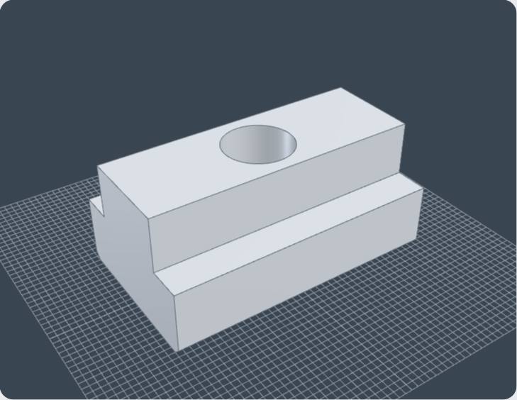
T-nut
For a 14 mm T-slot: a tongue left by two steps, an M12 tapped hole through.
Process sheet: 40 × 24 × 18 block, 5 ops
- Op 10 Mill Mill a step 5 in × 8 deep along the Top–Front edge, Ø10 cutter.
- Op 20 Mill Mill a step 5 in × 8 deep along the Top–Back edge, Ø10 cutter.
- Op 30 Drill Drill Ø10.2 thru, tap M12×1.75. Top face, X20 Y12 (hole A)
- Op 40 Mill Chamfer the Bottom–Back edge 1 × 45°.
- Op 50 Mill Chamfer the Bottom–Front edge 1 × 45°.
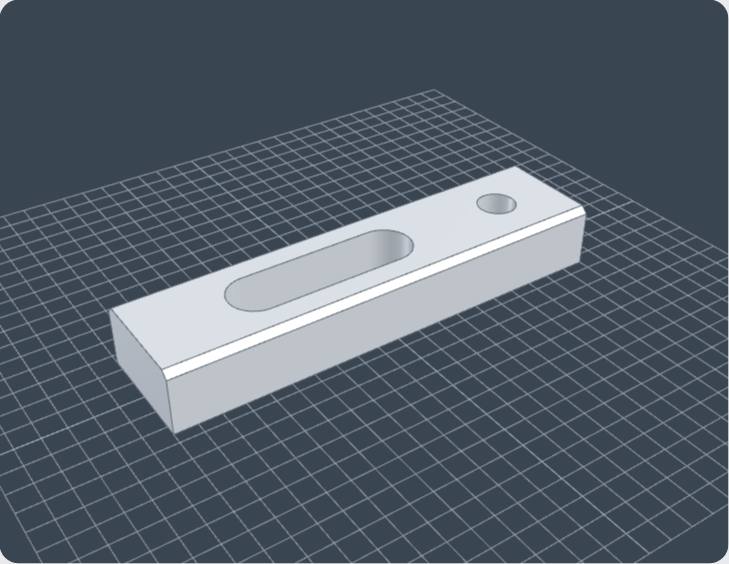
Strap clamp
A slot for the clamp stud, a tapped hole for the heel screw, chamfered top edges.
Process sheet: 100 × 25 × 14 block, 4 ops
- Op 10 Mill Mill a slot 12 wide, thru. Top face, X25 Y12.5 to X55 Y12.5.
- Op 20 Drill Drill Ø8.5 thru, tap M10×1.5. Top face, X85 Y12.5 (hole A)
- Op 30 Mill Chamfer the Top–Front edge 1.5 × 45°.
- Op 40 Mill Chamfer the Top–Back edge 1.5 × 45°.
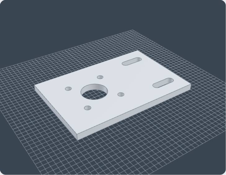
Motor mount plate
A spigot bore and four bolt holes for a flange motor, two slots to tension the belt.
Process sheet: 150 × 100 × 8 block, 4 ops
- Op 10 Drill Drill Ø30 thru. Top face, X50 Y50 (hole A)
- Op 20 Drill Drill 4 × Ø7 thru, on PCD 60, start 45°. Top face, centre X50 Y50 (holes B–E)
- Op 30 Mill Mill a slot 9 wide, thru. Top face, X115 Y20 to X135 Y20.
- Op 40 Mill Mill a slot 9 wide, thru. Top face, X115 Y80 to X135 Y80.
Square / flat bar: complex parts
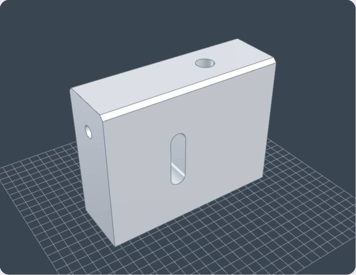
Air gun body
Passages drilled from three faces that meet inside, G1/4 and G1/8 ports, a slot for the trigger.
Process sheet: 90 × 30 × 70 block, 9 ops
- Op 10 Drill Drill Ø6 × 55 deep, flat bottom. Bottom face, X15 Y15 (hole A)
- Op 20 Drill Drill Ø11.8 × 14 deep, flat bottom, tap G1/4. Bottom face, X15 Y15 (hole B)
- Op 30 Drill Drill Ø6 × 80 deep, flat bottom. Left face, X15 Y55 (hole C)
- Op 40 Drill Drill Ø8.8 × 12 deep, flat bottom, tap G1/8. Right face, X15 Y55 (hole D)
- Op 50 Drill Drill Ø6 × 15 deep, flat bottom. Top face, X60 Y15 (hole E)
- Op 60 Drill Drill Ø8.8 × 10 deep, flat bottom, tap G1/8. Top face, X60 Y15 (hole F)
- Op 70 Mill Mill a slot 8 wide, thru. Front face, X35 Y25 to X35 Y45.
- Op 80 Mill Chamfer the Top–Back edge 2 × 45°.
- Op 90 Mill Chamfer the Top–Front edge 2 × 45°.
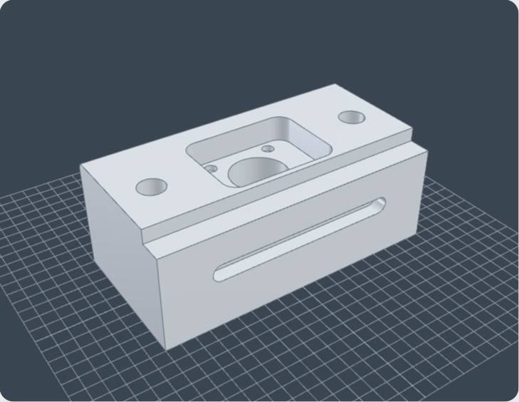
Bearing block
Skimmed and pocketed, a bearing bore with a tapped PCD round it, a step, a rounded edge and a slot.
Process sheet: 100 × 50 × 40 block, 9 ops
- Op 10 Mill Skim the Top face down 1.
- Op 20 Mill Mill a pocket 40 × 30 × 10 deep (corners R5), Ø10 cutter. Top face, X30 Y10.
- Op 30 Drill Drill Ø20 thru. Top face, X50 Y25 (hole A)
- Op 40 Drill Drill 4 × Ø4.2 × 12 deep, 118° point, tap M5×0.8, on PCD 32, start 45°. Top face, centre X50 Y25 (holes B–E)
- Op 50 Drill Drill Ø9 thru. Top face, X12 Y25 (hole F)
- Op 60 Drill Drill Ø9 thru. Top face, X88 Y25 (hole G)
- Op 70 Mill Mill a step 8 in × 6 deep along the Top–Front edge, Ø10 cutter.
- Op 80 Mill Round the Top–Back edge R4 (corner-rounding cutter).
- Op 90 Mill Mill a slot 6 wide, 5 deep. Front face, X20 Y20 to X80 Y20.
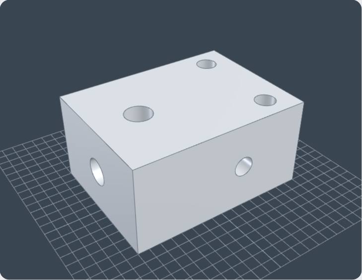
Hydraulic manifold
Three passages drilled from three faces that meet inside, G1/4 and G1/8 ports over them, two bolt holes.
Process sheet: 80 × 60 × 40 block, 8 ops
- Op 10 Drill Drill Ø6 × 25 deep, flat bottom. Top face, X20 Y30 (hole A)
- Op 20 Drill Drill Ø11.8 × 14 deep, flat bottom, tap G1/4. Top face, X20 Y30 (hole B)
- Op 30 Drill Drill Ø6 × 60 deep, flat bottom. Left face, X30 Y20 (hole C)
- Op 40 Drill Drill Ø11.8 × 14 deep, flat bottom, tap G1/4. Left face, X30 Y20 (hole D)
- Op 50 Drill Drill Ø6 × 30 deep, flat bottom. Front face, X50 Y20 (hole E)
- Op 60 Drill Drill Ø8.8 × 10 deep, flat bottom, tap G1/8. Front face, X50 Y20 (hole F)
- Op 70 Drill Drill Ø9 thru. Top face, X68 Y10 (hole G)
- Op 80 Drill Drill Ø9 thru. Top face, X68 Y50 (hole H)
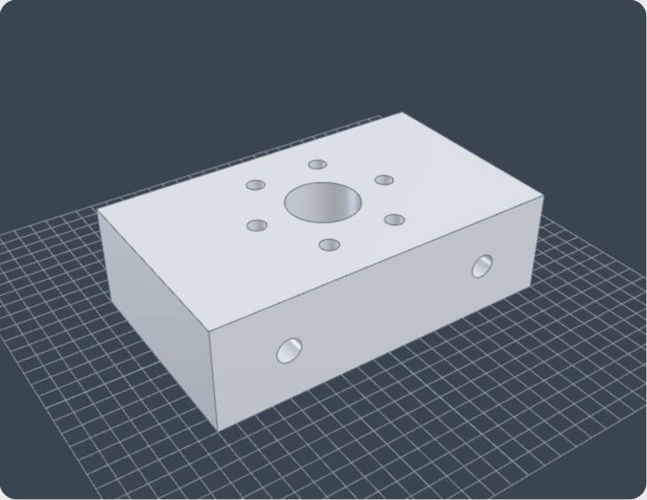
Bearing cover
A blind bearing recess with six tapped holes round it (measured from the recess), two M8 tapped holes in the side.
Process sheet: 100 × 60 × 30 block, 4 ops
- Op 10 Drill Drill Ø20 × 15 deep, flat bottom. Top face, X50 Y30 (hole A)
- Op 20 Drill Drill 6 × Ø5 × 12 deep, 118° point, tap M6×1, on PCD 40, start 0°. Top face, centre X0 Y0 from hole A (holes B–G)
- Op 30 Drill Drill Ø6.8 × 18 deep, 118° point, tap M8×1.25. Front face, X20 Y15 (hole H)
- Op 40 Drill Drill Ø6.8 × 18 deep, 118° point, tap M8×1.25. Front face, X80 Y15 (hole I)
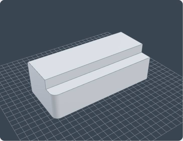
Fixture block
A step along one edge, a pocket underneath, a rounded corner, a chamfer and a locating hole in the end.
Process sheet: 90 × 40 × 30 block, 5 ops
- Op 10 Mill Mill a step 10 in × 8 deep along the Top–Front edge, Ø10 cutter.
- Op 20 Mill Chamfer the Top–Back edge 2 × 45°.
- Op 30 Mill Round the Front–Left edge R5 (corner-rounding cutter).
- Op 40 Mill Mill a pocket 50 × 20 × 6 deep (corners R4), Ø8 cutter. Bottom face, X20 Y10.
- Op 50 Drill Drill Ø8 × 30 deep, flat bottom. Right face, X20 Y15 (hole A)